
One of the big hurdles I encountered when doing my retro fit…and one that I found a hassle when pondering a change to forged pistons, was what were the parts I actually needed!!
The following list is designed to help the guys who may not have the benefit of an experienced Gen 3 engine builder, but need to get some parts lined up on the table to do stuff.
The list is split into four sections – sections –Basic technical specs of a standard stroke 6.1 hemi rotating assembly – Parts to complete a retro fit using carbs – a list of gaskets and fasteners you’ll need for any tear down or cam change – and some parts suggestions for an internal rebuild for a stroker or just a stronger standard stroke motor.
These lists are NOT comprehensive, but will at least give you an idea of what’s available and who makes what.
signed, your Editor.
6.1 Specs
Bore – 4.055
Stroke – 3.58
Rod length – 6.240
Pins – 2.55”, .9843”
Piston weight – 441 grams inc pin
Retro fit parts list
Ignition ECU – MSD 6-HEMI P# 6013 – This is for ignition only. so unsuitable for use if you want EFI.
ECU to coil Harness – MSD P# 88864 (Requires changes to factory cam and crank sensors to 07-10 5.7 Cam and Crank sensors)
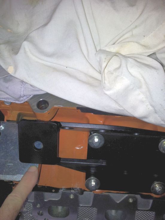
Engine mounts – TTI – MM57A
MP Flex plate adapter – P5153753
ATI Flex plate adapter (Recommended) – ATI915685
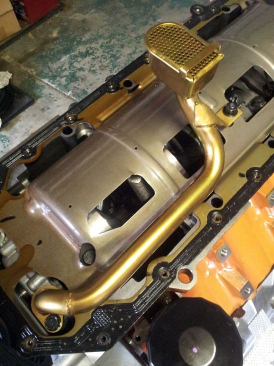
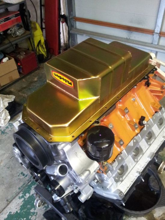
Milodon Pan/Sump – MIL31000 – (Note, also available are Weldtech, Canton Mecca, Charlies & Moroso- (Do your research!,Ed.)
Milodon Pick up – MIL18331
Milodon bolt kit – MIL85025
Milodon splash tray – MIL32010
Milodon pan gaskets – Mil40750
Mahle splash tray – OS32363
Milodon Oil dipstick – 22064
Lokar flexible transmission dipstick
Lokar universal accelerator cable
Lokar universal kickdown cable
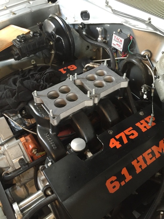
Manifold – Carb(s) or 4V Throttle Body
- OCP Dual Plane Single
- Edelbrock Dual Plane Dual Quad – (Small plenum volume, responds well to spacers)
- Ritter Drag pack (Requires scoop – 7.5” high)
- MP Drag Pack – (Requires scoop – 9” high)
- Indy Modman – Dual or Single (Recommended for use with supercharger only)
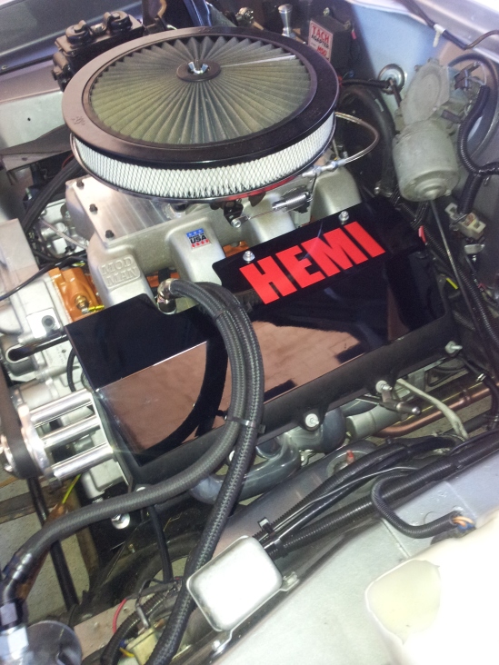
Air cleaner, Aluminium Radiator, Hoses, Electric Fans
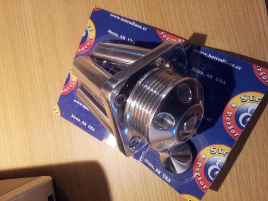
PS delete pulley (Bouchillion)
Headers – TTI long tube or Jeep SRT factory may fit
Remote oil filter set up or Dakota filter mount
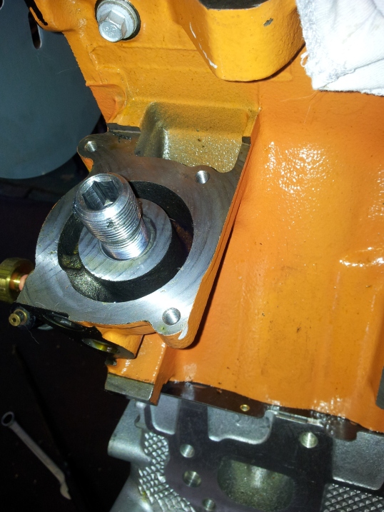
TTI oil boss block off plate – 0200-FBP
Idler pulley – 0489172AA, Screw – 06508247AA
Tensioner – 04861660AA, Screw – 06104221AA
Jeep 6.1 Nippondenso Alternator pre 2011 – 56044380AC, 56044380AH, (Use with external regulator) – The Jeep alt. provides for better inner guard clearance.
Fasteners and gaskets
Main Cap oil pick up stud # 6506333A
Main Cap bolt #6506272AA M12X1.75X91.2
Main Cap oil pick up stud # 6506333A
Main cap side bolts #6507697AA M8X1.25X45
Mopar Head Gasket 6.1 #5037592AC
Head Bolt #6506334AA
Head Bolt #6510280AA.
Screw-Connecting Rod #6509243AA
Head Gasket Sets – #Fel-Pro HS26366PT
Intake Gasket (Ports only) – Cometic #C5197 – Cometic Aramid Fibre
Intake Gasket inc Factory valley – MAHLE Original #MS19674
Exhaust Gasket – Fel-Pro #MS96964
Lower end gasket kit – #05170861AC
Std/Stroker rebuild parts.
Pistons – Probe SRS forged – #14868 – 491 grams inc pins – 9.88 comp – Rings – Total Seal ring pack – CR 1001 60 (1/16,1/16, 3mm).
Piston Kit – Mahle HMI220055F01 forged inc metric ring pack (1.5, 1.5, 3.0) – 429 grams – :10:1 comp
Piston kit – Wiseco K0112xs forged inc metric ring pack (1.2, 1.2, 3) – 460 grams – 11:1 comp
Piston kit – Stroker – Wiseco K471X05 forged inc metric ring pack – 445 grams – 10.5:1 comp
Camshaft – Crower camshaft degreeing bushings – 720007, 720008, 720009 (Use these with aftermarket pistons with valve reliefs ONLY)
T Chain – Manley 73205 DR 9 Key way – (Use with aftermarket pistons with valve reliefs ONLY)
Rear seal without retainer – #C5203 Cometic
Front seal – 53021585AD or Timken SL260028
6.2 / 5.7L – NON-MDS Lifter 5038784AC.


